16-channel GPS antenna splitter
(Downloads: Data Sheet, Manual)
In several use cases there is a need for providing a GPS reference signal to a variety of device with built-in receivers. Running separate Antenna cables to each of those GPS receivers is often difficult and cumbersome.
This includes, for example
lab setups where many cellular base stations with GPS clock reference input are operated
lab setups wit a variety of measurement devices that utilized GPS disciplined reference clocks
in-building distribution of GPS RF signals
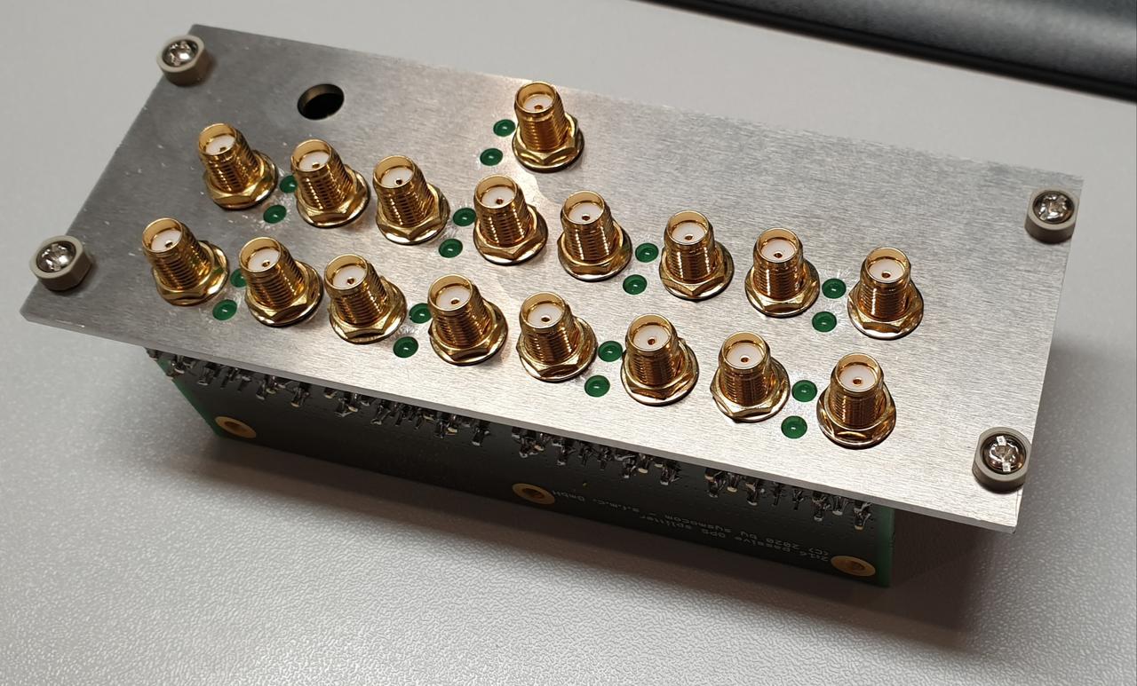
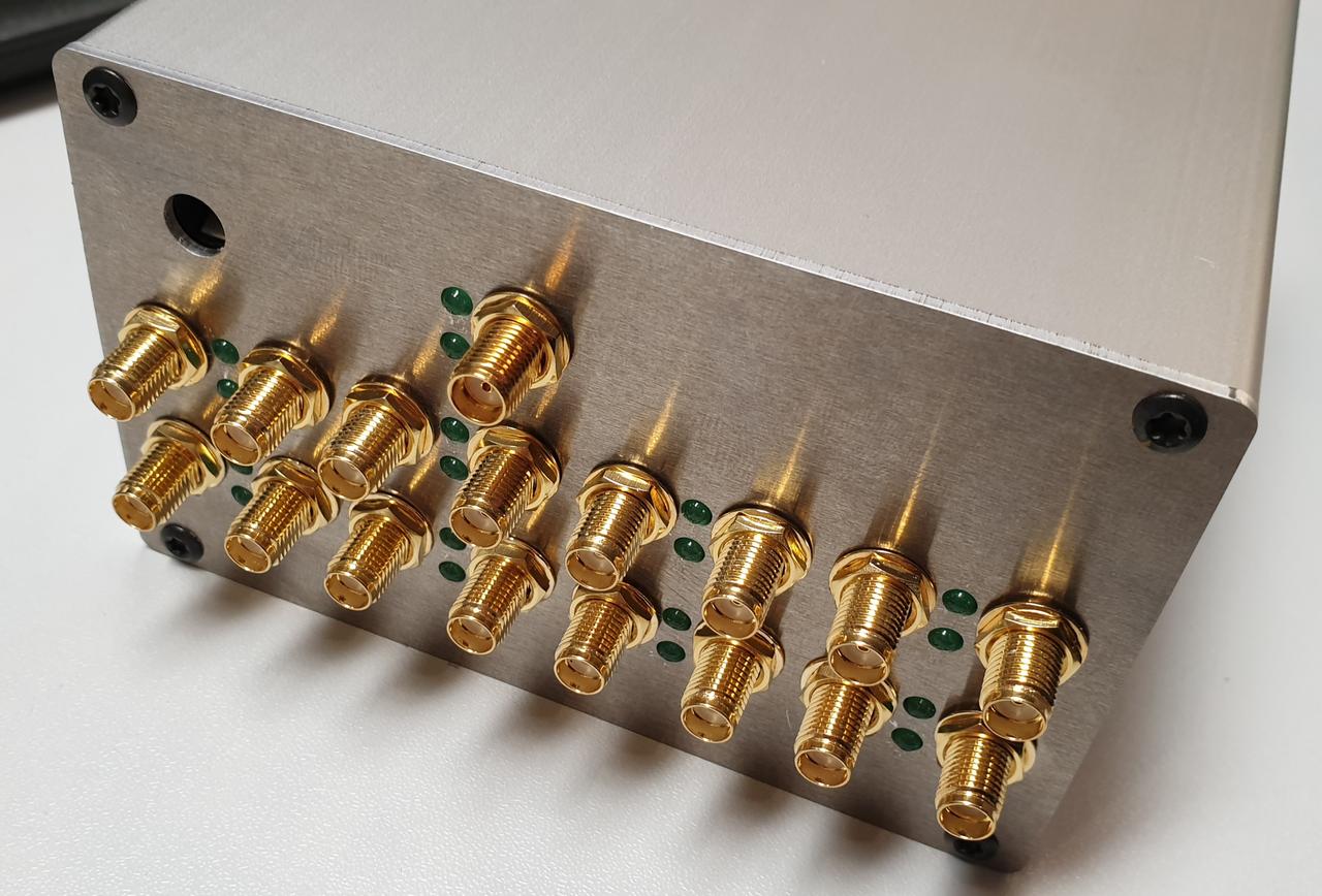
The sysmocom 16-channel GPS antenna RF splitter is the ideal solution for such setups. Its unparalleled number of 16 receiver-side RF ports allow for a large density of GPS receivers.
The GPS RF signal of a single GPS antenna (which can optionally be phantom powered by the splitter) is filtered, amplified, filtered again and then split (in two stages of 1:4 dividers) across 16 RF outputs.
Each output features an integrated DC-block and a dedicated LED to indicate if phantom voltage is supplied by the attached receiver or not. Supported biasing voltages on the output side are in the range of 3 .. 12V DC.
Form-Factors
The product is available in two form-factors:
a stand-alone extruded aluminum desktop enclosure - useful for portable operation on a lab desk (Product code: gps-spl-16-koh)
as a module for a 3U component carrier - a perfect fit for larger rack-mounted lab installation or in-building GPS RF signal distribution (Product code: gps-spl-16-bgt)
Technical Data
Electrical Specification
Supply Voltage |
12V DC / 300 mA, provided either via 5.5/2.5mm barrel or internal 2.54mm header |
Phantom Voltage to Antenna |
Selectable via jumper (none, 3V, 5V, external) |
Phantom Voltage from Receivers |
Supported range from 3V .. 12V DC |
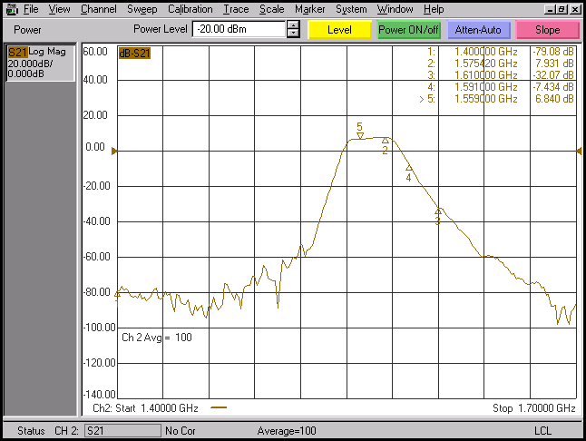
Overall RF System Gain |
8 dB typical @ 1.57542 GHz |
Passband |
1.57422 .. 1.57662 GHz |
RF Isolation (between outputs) |
20 dB (same 1:4 divider); 40 dB (different 1:4 dividers) |
Filtering |
|
RF connectors |
SMA, female, bulkhead mount |
Internal Filters |
2x EPCOS B39162B3520U410 reflective SAW filters |
Internal LNA |
1x 30 dB, 1.0 dB Noise Figure |
Absolute Maximum Input RF Power |
25 dBm |
Operating Temperature |
-40 to 85 centigrade |
Mechanical Specifications
All dimensions exclude the protruding RF connectors!
Variant |
3U component carrier |
Desktop Enclosure |
|---|---|---|
Dimensions (W x D x H) |
128.4 mm x 50.8 mm (10 DU) x 45 mm |
105 mm x 65 mm x 53 mm |
Weight (net) |
TBD |
TBD |
Order Code |
gps-spl-16-bgt |
gps-spl-16-koh |
Included Accessories
none