1:4 resistive splitter/combiner PCBAs
(Download the Data Sheet)
The rfcomb4r series features a couple of miniaturized 1:4 resistive RF splitter/combiners.
In applications where high insertion loss is desired, those type of splitter/combiners are significantly lower cost and smaller size than the usual RF splitter/combiners on the market, which are optimized for exceptionally low insertion loss.
A 1:4 resistive splitter/combiner is basically nothing else but five resistors connected together at one terminal. The theoretical insertion loss is 12dB, plus losses in connectors, substrate, etc.
Common features of all models:
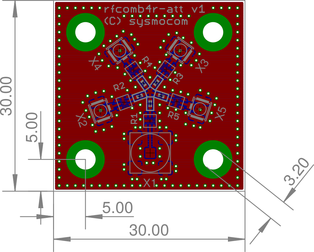
small, 30x30mm 4-layer printed circuit board
four mounting holes in the corners, spaced 25mm, intended for mounting using M3 screws/spacers
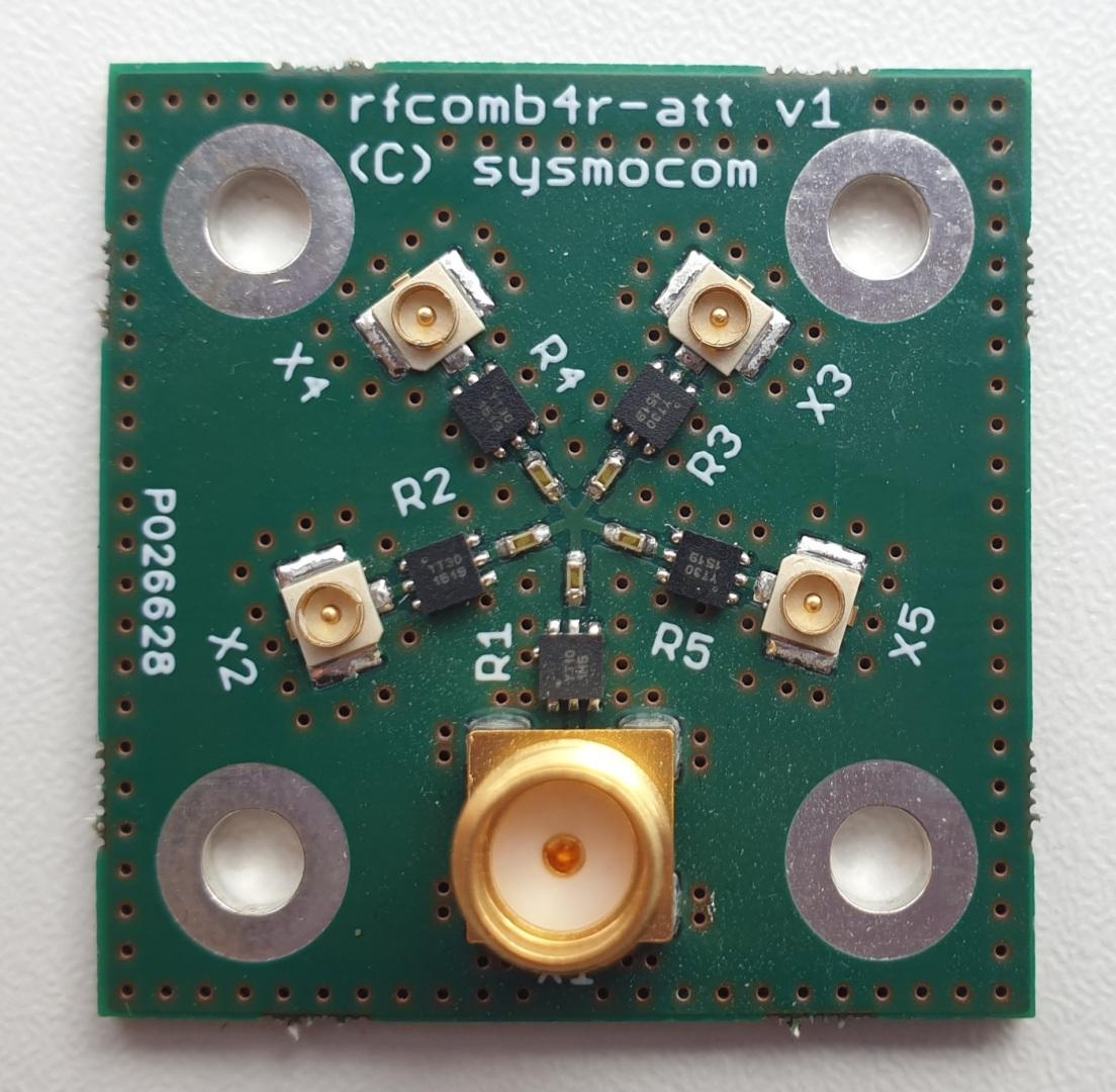
common port is SMT SMA jack
four tributary ports are IPX/U.FL, ideal for direct connection to cellular modems via IPX/U.FL pigtails
rfcomb4r
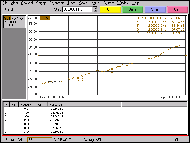
This is the basic variant with just the resistive splitter/combiner and no additional on-board attenuators. As a result, it features identical insertion loss (14dB) between the tributaries and the SUM port as isolation between the tributaries

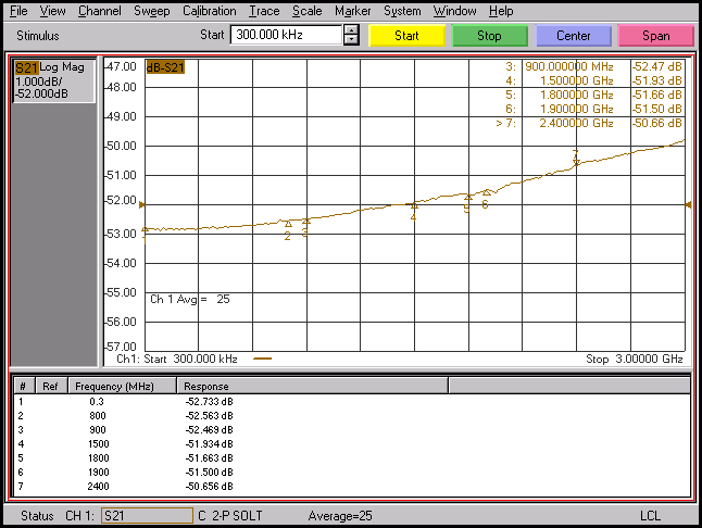
rfcomb4r-att30
This combiner features an additional on-board attenuation of 20dB in each tributary and 10dB in the SUM port. This results in an overall insertion loss of about 43dB. The isolation between tributaries is 10dB higher.

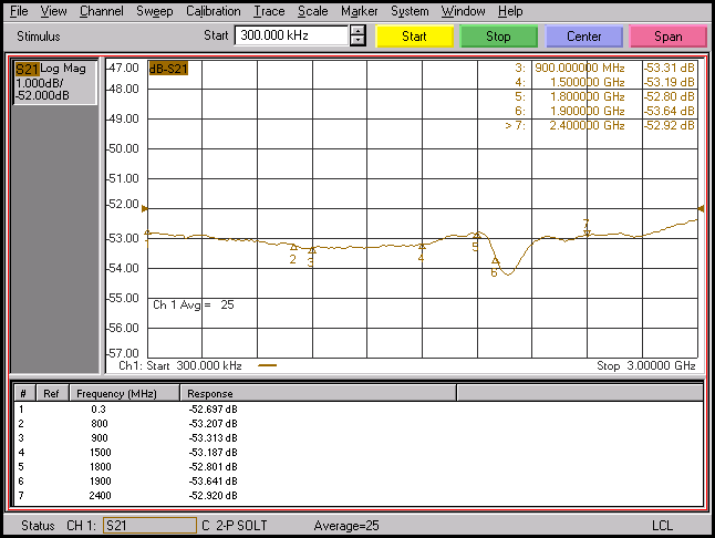
rfcomb4r-att40
This combiner features an additional on-board attenuation of 30dB in each tributary and 10dB in the SUM port. This results in an overall insertion loss of about 53dB. The isolation between tributaries is 20dB higher.
Mechanical Outline